# Gamma-Omega Original
## Quick Links
- [3D Printable Case](../cases/)
- [PCB](pcb/)
- [Ergogen Configuration](ergogen/README.md)
- Firmwares
- [QMK/VIAL Implementation](firmwares/QMK/gamma_omega/)
- [ZMK Firmware](https://github.com/unspecworks/zmk-config-gamma-omega)
- [Build Guide](BUILD_GUIDE.md)
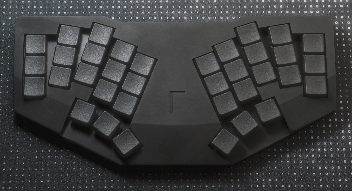
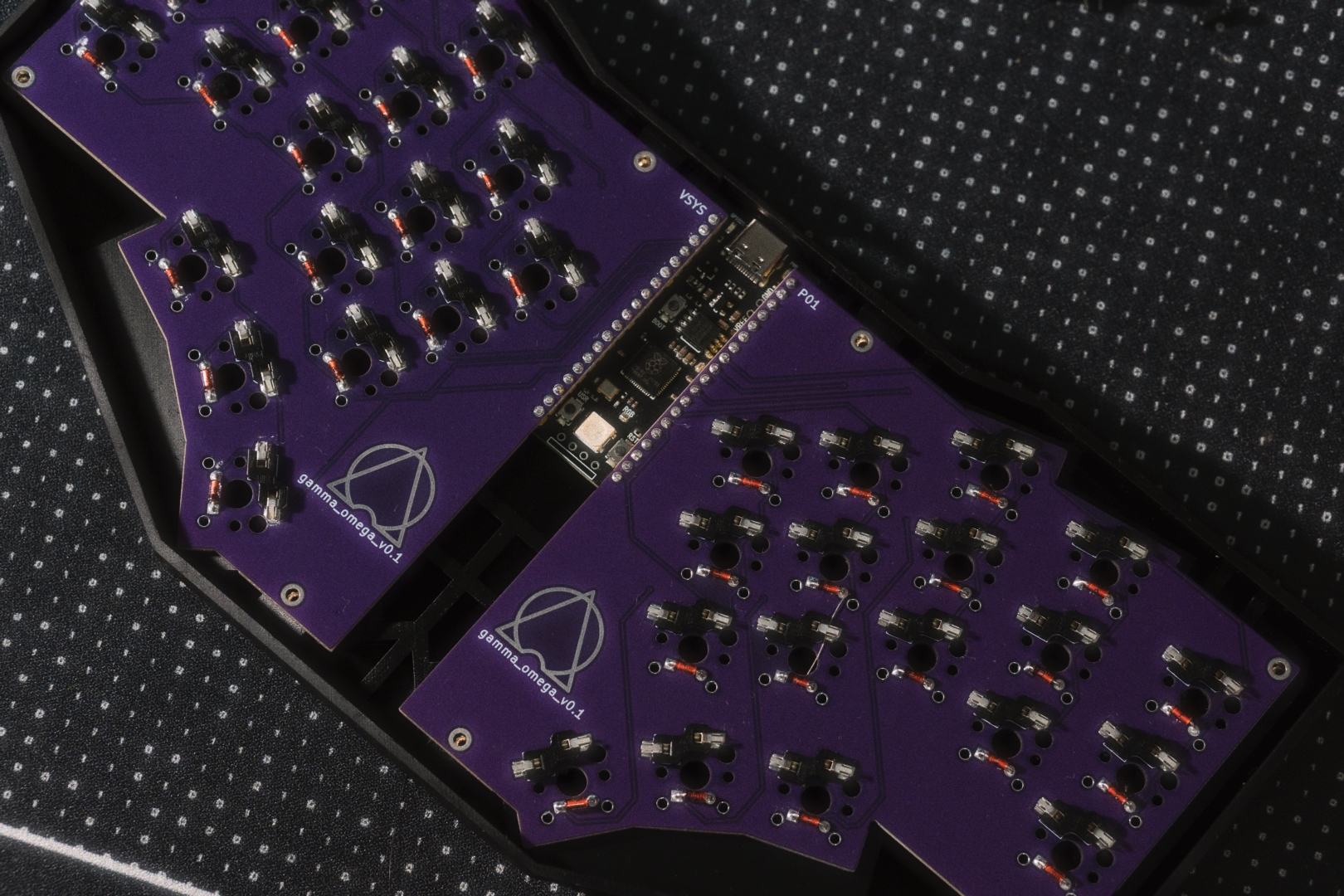
## Photos
 ## PCB design
This uses two identical reversible PCBs for the two halves of the keyboard, joined at the RP2040 controller.
This means some pins cannot be used as there isn't a matching pin on the other side,
for example GP0 and GP1 are opposite voltage pins.
This diagram sketches the [GPIO usage](../images/black-raspberry-pi-pico-pins.png)
(red and blue coloring following the convention for the two sides of the PCB).
The design assumes a specific Raspberry Pi Pico variant with GPIOs on pins 35 and 37 (GP29 and GP23),
which are not available on the original board design.
However the pairs GP13/18, GP14/17, and GP15/16 at the bottom of the board are unused,
so in theory the PCB could use those instead for compatibility with the original pin allocation.
## PCB design
This uses two identical reversible PCBs for the two halves of the keyboard, joined at the RP2040 controller.
This means some pins cannot be used as there isn't a matching pin on the other side,
for example GP0 and GP1 are opposite voltage pins.
This diagram sketches the [GPIO usage](../images/black-raspberry-pi-pico-pins.png)
(red and blue coloring following the convention for the two sides of the PCB).
The design assumes a specific Raspberry Pi Pico variant with GPIOs on pins 35 and 37 (GP29 and GP23),
which are not available on the original board design.
However the pairs GP13/18, GP14/17, and GP15/16 at the bottom of the board are unused,
so in theory the PCB could use those instead for compatibility with the original pin allocation.